At work, I am developing a platform for simulating robots. Recently, I delivered a computer that developers can connect to, send jobs to a simulated robot and test their code. But there are a few problems with this process. You could connect to the computer only to find out that someone else is already using it, people sometimes don’t bother to disconnect, and someone could leave the simulation running when there is no reason to (we must always remember to be environmentally conscious).

So I have a problem statement, and now I need to find a solution. Whenever I’m dealing with a real-world problem (however serious), I try to solve it in its entirety. It is a great exercise on product development with many learnings along the way. You always gain something whether it is new ways of working with a CAD software, a new service for creating PCB designs, or more tricks for text processing in bash. What follows in the next sections is a walk-through of the process of turning the idea of a more accessible interface for the simulation computer into a deliverable product.
Concept
What I need is a means of getting information about the status of the computer before taking any action. The fastest way of achieving this is with a visual aid. I could have an LED that can quickly tell me what is going on at a high level. Then a screen can give me a list of users so that I can contact them and coordinate on how to share the resource. So, I need to build a device with a microcontroller, a screen, and an LED, which will accept and display information from the computer. To complete the concept, I will also add a button that when pressed, it will do a cleanup by disconnecting all users and killing the simulation. On the computer side, there will be a process that will be gathering data and forwarding them to the device. At the same time, the process will be waiting for commands from the device for doing a cleanup.
Design
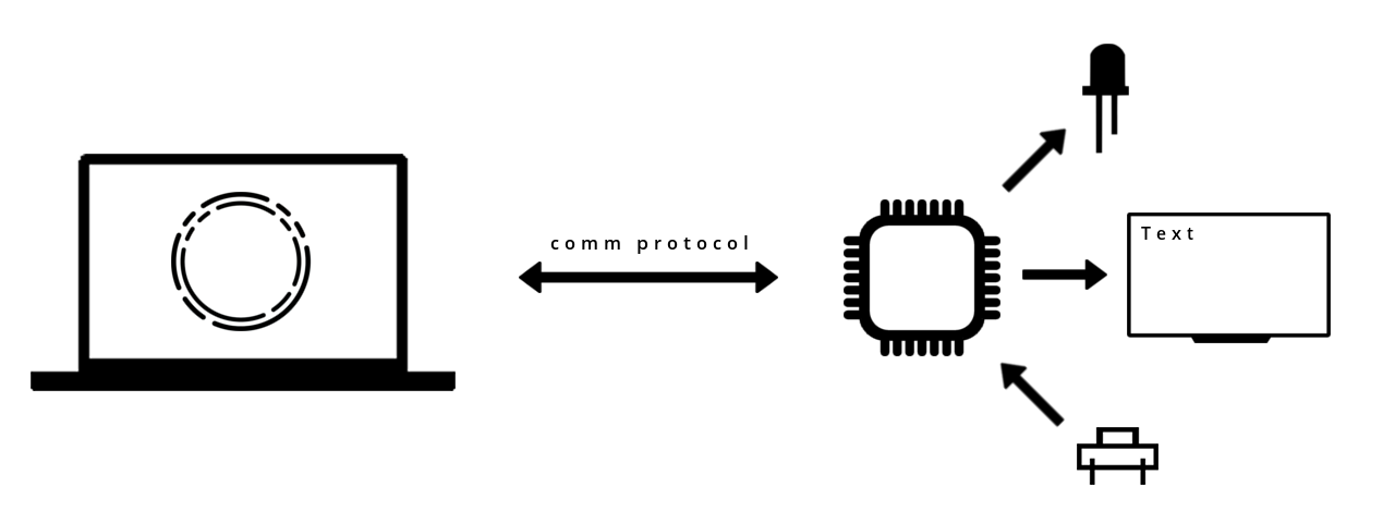
Time to identify requirements and design this thing. The computer is given, so I only have to select a microcontroller (uC) and make sure they can communicate with each other. Any uC with a Serial port and a USB interface will do. I’m considering Serial communication here since it’s simple and the device will already be connected to the computer for power anyway. I’ll come back to the uC, but for now, let’s consider the LED. I want to have multiple colors. For this, I can go with a DotStar LED. DotStar LEDs are RGB, they have a generic SPI interface, and they require no external components. For the screen, I can go with an SSD1306 OLED display. It’s cheap and straightforward to use with an I2C interface. Not only that, but there is also the Wemos LoLin32 board that hosts an ESP32 with an SSD1306 OLED, so I can pick this board and kill two birds with one stone. Finally, I need a tactile switch, nothing special about this.
The communication between the computer and the ESP32, as mentioned above, will be realized through Serial. But to make them talk to each other, I must establish a protocol. The information I want to convey to the ESP32 is whether the simulation is running and the list of connected users. The following message format is a way to achieve this:
#<PS_FLAG> <USER_0>,<USER_1>,...,<USER_N>\n
The message starts with a #. The # plays the role of synchronization. Then follows a boolean variable {0,1} for the status of the simulation, a space, and a comma-separated list of user information (it can be anything). The message ends with a newline.
The message that goes from the ESP32 to the computer, when the button is pressed, is always the same. So, let’s keep things simple and just send a GTFO message, as in Get The Fuck Out.
PCB
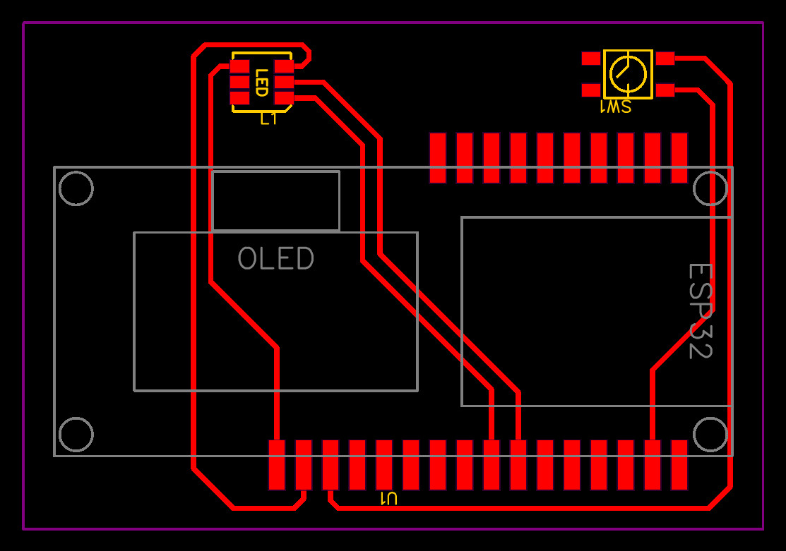
I’ve selected the components for the device, and now I must define their connections. For this, I have to design and make a PCB. The name EasyEDA has come up a lot over the years, so I thought I’d give it a try. Before starting designing the schematic, I had to search the available libraries and find the parts. Thankfully, other people have already created a part for the Wemos Lolin32 board, but sadly, it wasn’t usable. I only have single-sided copper clads, so I wanted to keep everything on one side. I decided that I would bend the pins of the female headers, on which the board will sit, and thus turn them into SMD components. So then I had to modify the part in EasyEDA. I copied it and turned the PTH pads into SMD pads, and the WEMOS Lolin32 OLED SMD part came to be (you can search for it at EasyEDA). Having all the parts, I could then design the schematic, move over to the PCB editor, position the components, create the traces and finally export the Gerber files.
The Gerber files describe the details of the board. These files have to go through a CAM software in order to be compiled into gcode which the CNC can read and then translate into commands for the motors. The first step that the CNC performs is called PCB isolation. What it does is engrave around the PCB traces in order to separate the traces from the rest of the copper area. The next step in a PCB with through-hole components would be the drilling of the holes, but it’s not applicable in this case. The final step is milling. The board outline is milled away so that the board can take its final form.
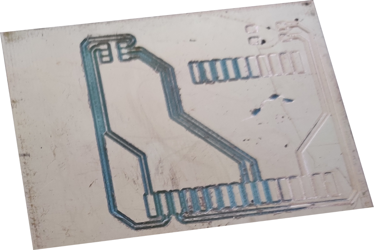
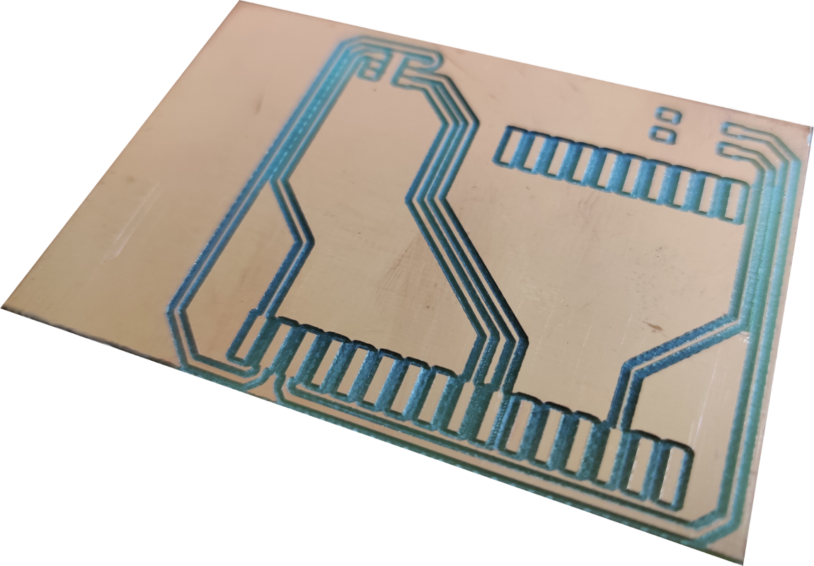
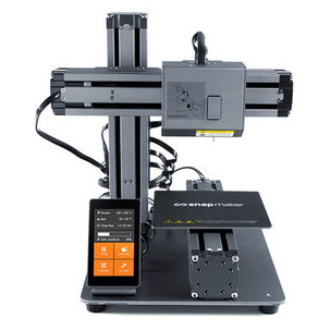
PCBs require some very detailed work. Even the slightest imperfections on the CNC can have a significant effect on the result. The alignment of the bit with the rotor and the leveling of the bed are two factors that can make or break a job. If the bit is not centered with the rotor, an effective diameter is created that is a multiple of the real diameter of the bit. So, instead of engraving 0.1 mm channels, you could be engraving 0.5 mm and make your traces disappear entirely. Then, if the bed is not leveled, there will be some areas on the board where the traces will not show up and others where the cuts will be too deep or the bit will break. A respectable machine should support calibration procedures to correct for these errors. Otherwise, you have to improvise and compromise. As you might have guessed, I’m not happy with my Snapmaker. To make this work for my board, I had to increase the width of the traces to 0.8 mm (so, in the end, I’m left with traces that are at least 0.1 mm wide) and manually adjust the bed by measuring its distance to the bit at different positions.
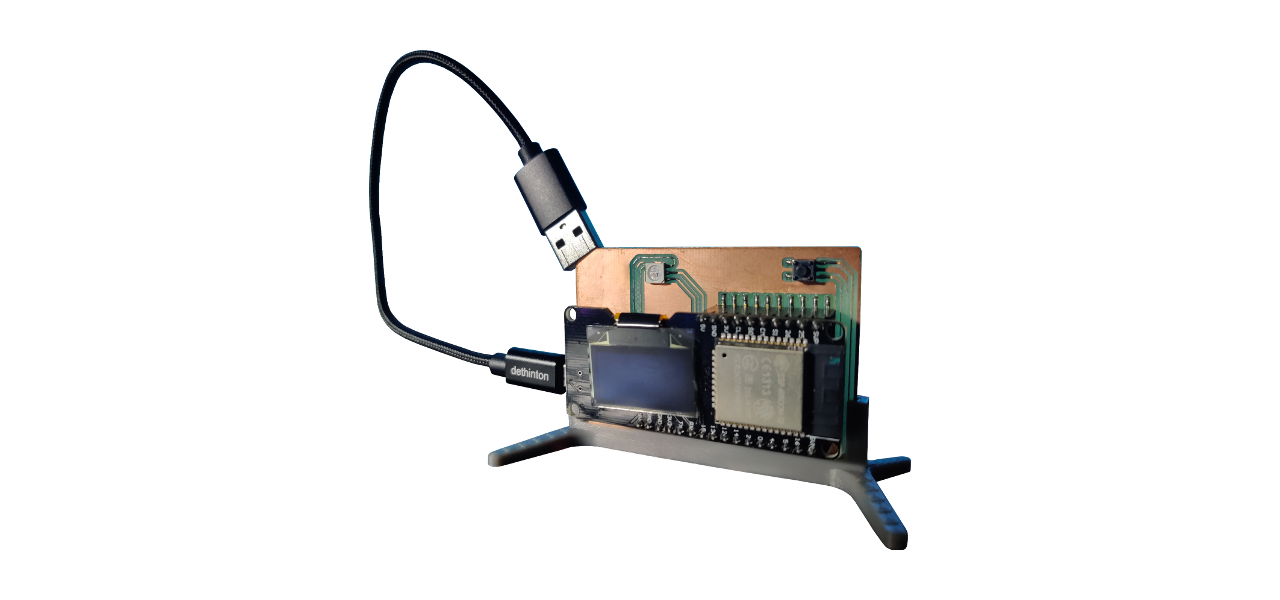
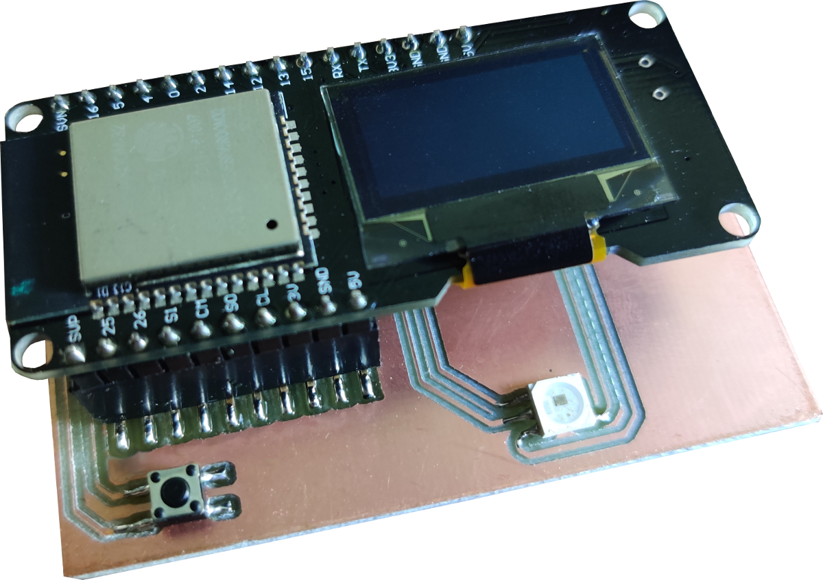
I collected the parts, created the board, and now it’s assembly time. I soldered everything on the board and with that, the hardware is ready.
Firmware
An ESP can be programmed with the Arduino IDE. Thus, the code was set up as an Arduino library that defines the necessary classes for the project and an Arduino sketch that implements the control loop. There are conceptually four entities that comprise this project: the parser, the display, the LED, and the button. The parser listens to the Serial port and parses incoming messages. The display reads a message and writes on the display the relevant information. The LED reads a message, infers the current state, and sets the appropriate mode and color on the actual LED. The button is associated with a pin on the board and, in the event of a press, sends a message to the computer. Having defined these entities, the control loop then looks like this:
void loop() {
  parser.update();
  display.update(parser.msg);
  led.update(parser.msg);
  button.update();
}
The parser retrieves the next message if there is one, which is then given to the display and LED to update their stuff, and the button polls its input and sends a message if the switch is pressed.
Something that became relevant when I was testing talking to the device is knowing whether communication has been established between the computer and the device. I decided to make use of the screen. When there is no communication with the computer, the screen will display a default image, and when there is communication, the screen will display a list of users. To make it possible to display an image on the SSD1306 screen, the image has to be converted to the xbm format. This can be done at convertio. You give it, for example, a jpeg and the output is a file that contains the image defined as a C array which can then be included in the sketch.
#define image_width 128
#define image_height 64
const uint8_t image_bits[] PROGMEM = { 0x00, 0xF8, 0x1E, 0x0D };
Driver
The device driver is realized as a Python script that periodically sends messages to the device and listens for messages from the device. It is parameterized by three Shell scripts (process.sh, users.sh, gtfo.sh), so a user can adapt the driver for their own use case. process.sh returns the state of the simulation, users.sh gives the list of users, and gtfo.sh is responsible for kicking the users out and killing the simulation.
Testing
With all the pieces on the table, comprehensive testing begins. The goal is “simply” to make the device always work. In this particular case, I encountered problems with the Serial port. Firstly, when the port is closed, you have to remember that the ESP reboots (otherwise you are left scratching your head). And secondly, if the port is not closed gracefully, the ESP can crash, and then you have to either try to reopen the port a few times or reconnect the device to the computer.
User Experience
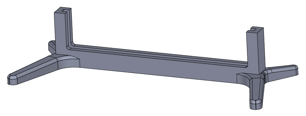
At this point, I have a prototype. But how do I turn this into a “product”? I have to think about the user experience. The device is meant to be present on a desk next to a computer. So what I need now is something that will allow the device to sit firmly on the desktop. For this reason, I designed a stand that the device can slide into and stay there. I 3D printed the stand on the Snapmaker.
The next question that needs an answer is how does someone get the device working without having to look into the technical details? For this, I need an installation script. The script will place all files to the right directories and make sure that the driver is started every time the computer boots. This was implemented with a systemd service which allows to autostart, stop, and restart the driver. Now the user can be given these simple steps to follow

and happily carry on with their work.
Conclusion
So that was fun. I managed to make a PCB on my CNC, got upset with the shortcomings of the CNC, got frustrated with the poor editor in EasyEDA, but overall enjoyed completing another project. I consider going through this entire process of problem solving really valuable. It makes the steps clear and takes the fuzziness away from each step, so you can better structure your work and get things done.
You can find information on all available resources on GitHub.