Last time, we worked on creating a basic gazebo simulation. We arranged our gazebo resources, created a map for our world, and configured the launch of a robot model and the navigation stack, such that we are able to send a goal and have the robot autonomously navigate to it. This time, we build upon that simulation by spawning a second robot in the world with a target on its back, which our robot will try to follow. More specifically, we are going to work on an application of visual servoing, and in the meantime, we’ll have the chance to explore how to configure a multi-robot simulation, apply textures to models, enforce constraints between models, and have a robot follow a visual marker that is constantly moving in the world.
Preparation
We will continue working on the same grobot repository we introduced in the last post. It has been updated to include the new material we will go through this time. Either git pull grobot and rosdep install to get the additional dependencies, or delete the grobot_ws workspace all together and repeat the steps from the beginning.
> source /opt/ros/$ROS_DISTRO/setup.bash
> mkdir ~/grobot_ws
> cd ~/grobot_ws
> wstool init src https://github.com/nlamprian/grobot/raw/master/.grobot.rosinstall
> rosdep install --from-paths src --ignore-src --rosdistro=$ROS_DISTRO
> catkin build
> source devel/setup.bash
Multi-Robot Simulation
In gazebo, we can spawn as many models as we want, and even multiples of each one. We’ve seen this already in our example world, where we happened to have two instances of a couple of models. So, we should be able, in the same way, to spawn a second robot in the world, right? Not so quickly. Gazebo wouldn’t complain if we did that, but the resulting configuration would be broken. Let’s consider what would happen:
- cmd_vel topic: both robots would listen to the same command topic and execute the same commands. A message aimed for one robot would get received by the other robot too
- sensor topics: both robots would publish their sensor data to the same topics, thus creating sequences of conflicting information
- tf: both robots would define the same base_footprint frame in tf, which would keep jumping between the two robot poses
- nodes: any ROS nodes that rely on sensor data wouldn’t function properly, because of all of the above
Fortunately, this is easily fixable. We can configure our resources with namespaces, and use a different namespace for each robot, such that there are no conflicts anymore. Inside the robot launch files, we need to:
- define everything within
<group>tags with the name of the robot,<name>, as a namespace. This means any parameters we upload to the parameter server, and any nodes we run, will be under this namespace. E.g.,/<name>/robot_description - set the
tf_prefixparameter with the name of the robot,<name>, as a value. This parameter will be picked up by some nodes and be prepended to any tf frames they are broadcasting. E.g.,base_footprintbecomes<name>/base_footprint
There might be some nuances in the way we have to launch some of the nodes, but the above two steps, in the most basic form, is all we have to do. Having configured a robot bringup with namespaces, we can get a simulation with more than one robot like so:
<launch>
  <include file="$(find gazebo_ros)/launch/empty_world.launch">
    <arg name="world_name" value="$(find grobot_gazebo)/worlds/example.world" />
  </include>

  <include file="$(find grobot_bringup)/launch/<robot-bringup>.launch">
    <arg name="name" value="karl" />
  </include>

  <include file="$(find grobot_bringup)/launch/<robot-bringup>.launch">
    <arg name="name" value="hank" />
  </include>
</launch>
You can examine such a multi-robot simulation example by running
> roslaunch grobot_bringup patrols.launch
This will launch gazebo and spawn two turtlebot3 burger models with the names karl and hank. If we do a rostopic list, we will notice that there are two instances of each topic, that was available before for one robot. For example, karl listens to the karl/cmd_vel topic for commands, and hank listens to the hank/cmd_vel topic. And if we do a rosrun tf view_frames, we’ll see that each robot has its own unique tf tree.
Textures
We are jumping now to a different topic. We are going to create a model for the visual marker that our robot will later follow. If we were to do such a thing in reality, we would probably look for a surface where we would stick the marker on. We’ll do something similar in gazebo.
Technically, we are going to apply a texture to an object. We have seen this before in our example world. This is how the tile pattern was put on the walls.
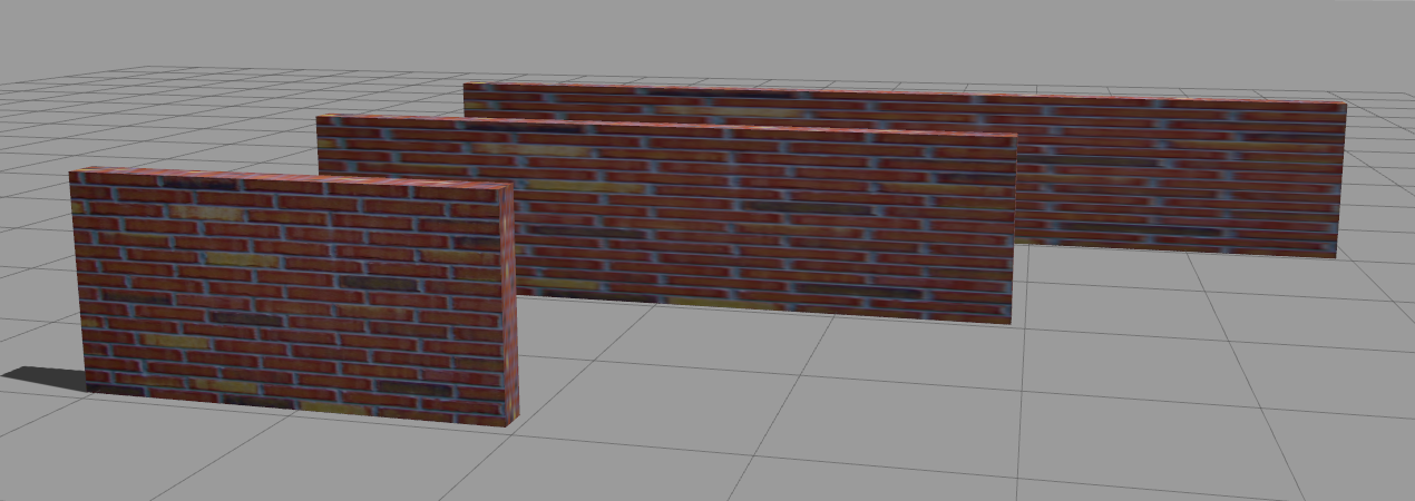
A texture, in its simplest form, is an image which is applied on each face of a geometry. The image is streched in order to cover an entire face. This is why, in the figure above, we see that the longer a wall gets, the longer and blurrier the tiles become.
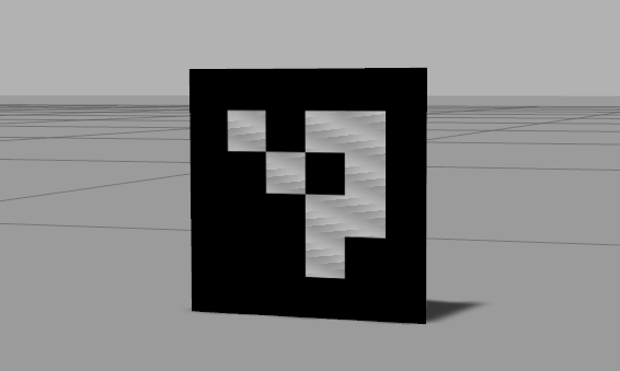
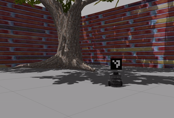
Let’s now look into the marker itself. We’ll use an ArUco marker. For the purpose of this tutorial, we only need to know that this is a marker which can be observed with a 2D camera, and have its 3D pose within the world extracted from the image.

This is what the visual description with the material looks like:
<visual name="visual">
  <pose>0 0 0 0 0 0</pose>
  <geometry>
    <box>
      <size>0.0001 0.15 0.15</size>
    </box>
  </geometry>
  <material>
    <script>
      <uri>model://aruco_marker/materials/scripts</uri>
      <uri>model://aruco_marker/materials/textures</uri>
      <name>Marker</name>
    </script>
  </material>
</visual>
And this is the file structure of the model:
aruco_marker
├── materials
│   ├── scripts
│   │   └── marker.material
│   └── textures
│       └── marker.png
├── model.config
└── model.sdf
You can examine the complete model in the grobot_gazebo package. Having this model, we can finally spawn the marker in the world.
Model Constraints
Now that we have a model for the marker, we need to attach it to a robot so that we get a moving target. It’s going to be pretty straightforward.
When we send an SDF description to gazebo and ask it to spawn a model, gazebo creates all the necessary links and joints in order to reconstruct the model. We have the possibility to do the same ourselves. That is, we can create a joint between two links, and those links can even belong to two different models. We can take advantage of this to create a fixed joint between the robot and the marker, thus constraining the marker and having it move with the robot.
We’ll keep it simple here and use an existing plugin to create the joint. We haven’t talked about plugins yet, and we might revisit them in the future, but basically, plugins are how we add functionality to gazebo. Plugins have a type that affects their initialization and lifetime, but ultimately, they all behave the same way. They wait for internal (gazebo) or external (ROS) events, and they respond, for example, by actuating a joint in the world or publishing a sensor message. If you are interested to know a bit more, you can have a look at the Plugins 101 tutorial.
The plugin we are going to use is the gazebo_ros_link_attacher. What the plugin does is offer ROS services we can call to attach or detach a fixed joint to two existing links. gazebo_ros_link_attacher is a world plugin. This means we enable the plugin by adding its configuration in the description of a world.
<world name='default'>
  ...
  <plugin name="ros_link_attacher_plugin" filename="libgazebo_ros_link_attacher.so" />
  ...
</world>
This has already been done in our example world. If we start world.launch and list the available services, we are also going to see those offered by the plugin.
> rosservice list
/link_attacher_node/attach
/link_attacher_node/detach
...
How the plugin works is, given two links in a certain configuration, a joint is created that locks the two together. In other words, the initial poses of the links matter. This means we need to control the relative pose between the two links (and by extension, models), before we call the attach service.
Here is the plan for attaching the marker to the robot. We’ll use a script to make a few service calls. The script will pause the simulation, get the current pose of the robot, compute the pose of the marker based on the robot pose, spawn the marker in that pose, attach the marker to the robot, and finally resume the simulation. We are pausing the simulation, so that we know that nothing moves while we are in the process of attaching the marker to the robot. You can find this script in spawn_marker_on_robot in the grobot_utilities package.
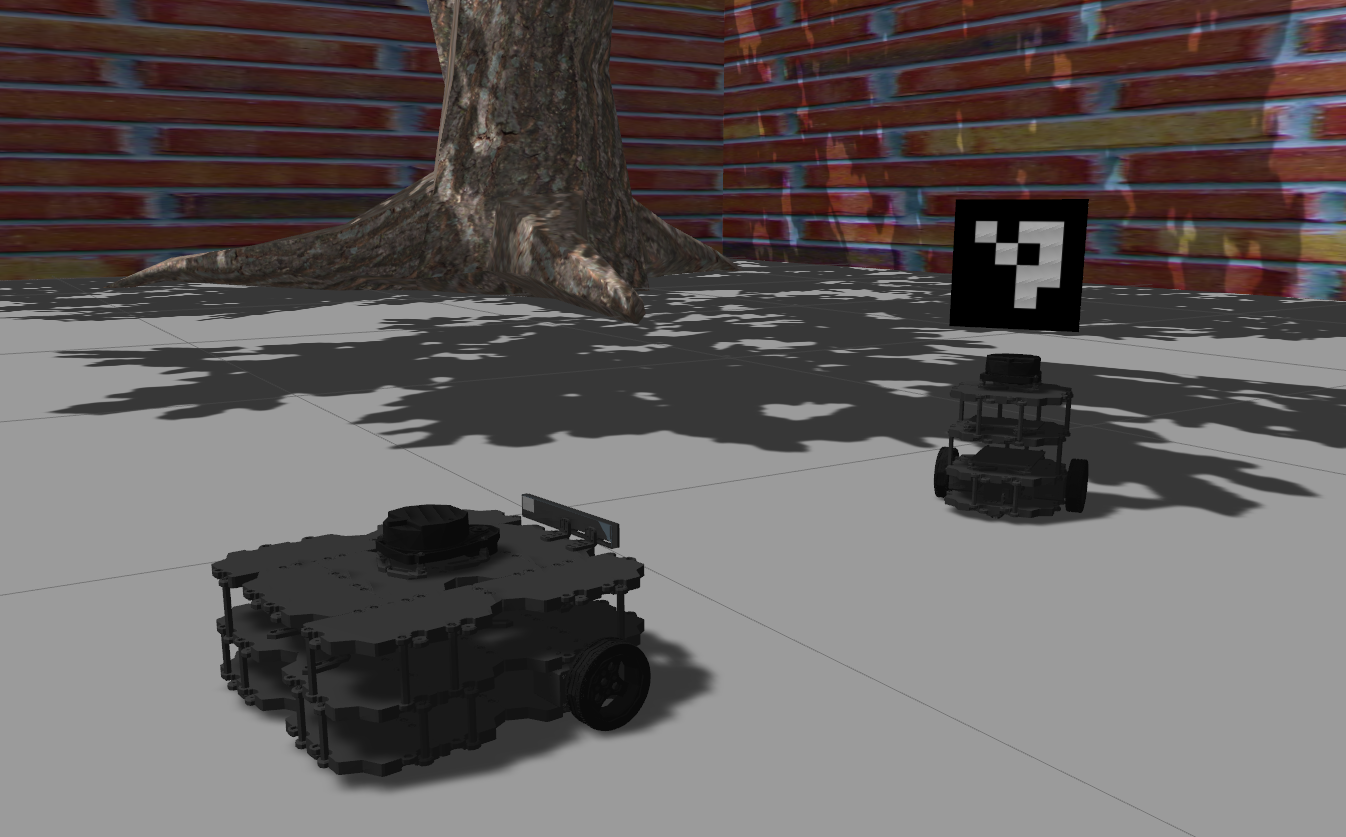
We are implementing this process in a node so that we can launch the node along with the rest of the robot bringup. The node will wait for the robot to show up, spawn and attach the marker, and then exit. To see this in action, you can run the patrols.launch once again, but this time with the has_marker parameter enabled. It will launch the same two turtlebot3 burger robots, but with two markers on top of them.
> roslaunch grobot_bringup patrols.launch has_marker:=true
Visual Servoing
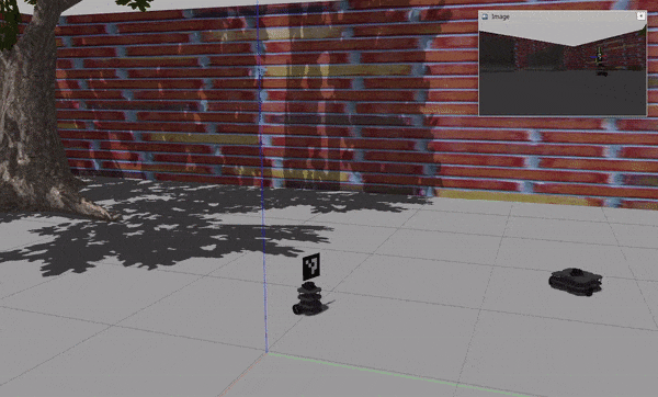
We are done with the gazebo topics for today. It’s now time for a fun application. We will make a waffle robot follow a burger robot with a marker. The waffle version of turtlebot3 has a depth camera which also publishes RGB images. If we start navigation.launch and give a goal to the robot, we can observe the live stream from the camera in the bottom left corner of rviz. We will use this camera to perceive the burger robot in the environment, and then try to follow it. Let’s consider what needs to go into this experiment. We have to:
- spawn a waffle robot
- spawn a burger robot, with a marker, that patrols an area
- be able to detect an ArUco marker in an image and get its transformation
- have a controller which implements a closed loop system that uses marker transformations as feedback in order to make the robot behave as described
We have already dealt with the first two points. What about detecting ArUco markers? For this, we will use the aruco_detect package. aruco_detect subscribes to a camera topic, and looks for markers in the images it receives. If a marker is detected, the node publishes its 3D transformation. All we have to do is provide the right parameter values for our own setup, and then the node will do the rest. Beware that the node is quite resource-intensive, and combined with gazebo, they will starve your computer.
<node name="aruco_detect" pkg="aruco_detect" type="aruco_detect">
  <param name="image_transport" value="compressed" />
  <param name="publish_images" value="true" />
  <param name="fiducial_len" value="0.15" />
  <param name="dictionary" value="0" />
  <param name="do_pose_estimation" value="true" />
  <param name="ignore_fiducials" value="" />
  <param name="fiducial_len_override" value="" />
  <remap from="/camera/compressed" to="/camera/rgb/image_raw/compressed" />
  <remap from="/camera_info" to="/camera/rgb/camera_info" />
</node>
In our case, aruco_detect has been configured to listen to /camera/rgb/image_raw for sensor_msgs/Image messages and publish fiducial_msgs/FiducialTransformArray to /fiducial_transforms. A fiducial transform message contains a marker id and a 3D transformation that tells the position and orientation of the marker with respect to the camera.
Last but not least, we need to figure out how we are going to control the robot. The goal of our control algorithm is to maintain a certain pose relative to a given target. The idea of vision-based control is about driving a robot with visual feedback. We will use the extracted information from the camera images to control the robot. So, for every fiducial transformations message, our control loop will act as follows:
- if marker is not detected
- if enough time has passed, start exploration
- if marker is detected
- if exploration is in progress, cancel exploration
- compute global navigation goal
- send navigation goal
To follow a target, we need to first see the target. If the target is not in the camera’s field of view, we cannot just stay idle, as it might never show up. So we need to start exploring the space. We will consider two simple approaches:
- move to a vantage point where we can expect the target to appear
- rotate in place 360 degrees to observe the space all around
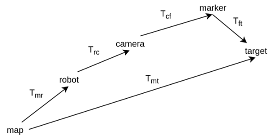
Given that we see the marker, and we have its transformation, \(T_{cf}\), we need to compute the navigation goal, \(T_{mt}\), for the robot. The marker transformation is in the camera frame. We need to first express it in the robot frame, and then the map frame. The robot to camera transformation, \(T_{rc}\), is defined by the URDF of the robot. The map to robot transformation, \(T_{mr}\), is estimated by localization. tf can do all these calculations, and give us the marker in the map frame, \(T_{mf} = T_{mr} T_{rc} T_{cf}\). Then, we only need to apply the marker to target transformation, which is defined by us, to get the desired pose of the robot.
move_base has two interfaces for sending navigation goals. One is a topic, move_base_simple/goal, and the other is an action, move_base. We use the topic to continuously send goals as we receive marker transformations. But we use the action when doing exploration so that we have some feedback. In the case of the ‘rotate’ exploration, for example, we want to keep going as long as we don’t see the marker. For that, we need to know when the robot has reached the commanded orientation so that we send the next one.
What was discussed is implemented in the follow_marker node in grobot_navigation. To see it all in action, you can run the visual_servoing.launch with your preferred exploration strategy.
> roslaunch grobot_bringup visual_servoing.launch exploration_strategy:=move_to_target
> # or
> roslaunch grobot_bringup visual_servoing.launch exploration_strategy:=rotate
It doesn’t take long to notice that the approach is unreliable. The robot frequently loses track of the marker. The problem is that we are giving a goal to the robot and letting it freely navigate. In this example, we implemented our algorithm as an application on top of move_base. In a real scenario, we would have to integrate our additional requirements into the navigation planner. The goal would be to make sure that the robot keeps track of the marker and to optimize its trajectories by anticipating where the marker is going to be.
Conclusion
We’ve seen how we can create and configure multiple resources in a simulation. We’ve worked on an application where we controlled a robot with input from a camera and had it follow a marker. The result was inadequate, but it showcases that by combining gazebo and ROS, we get a platform where we have all the freedom we need to experiment. So, what are you going to try next?