Back in November, I received my Snapmaker A350, along with its enclosure. It arrived almost one year after I ordered it. That was ok since I went into it with the right expectations. I already had the Snapmaker Original, and my experience with it was mostly positive. When the Kickstarter campaign for the Snapmaker 2.0 was released, I initially hesitated to click the button. The potential of the larger platform was intriguing, but the cost was high. It only took me a few project ideas and a bit of research to outsource them to convince myself finally. The prices that some “professional” services out there ask are sometimes just outrageous. I love being creative, and situations like this put a damper on the fun. And to that, I say, welcome Snapmaker 2.0.
The Machine
The unboxing experience with any Snapmaker product always feels premium. The team does a great job there. The build quality of the hardware feels great as well. You see all of this, and you get excited about what is to follow. Unfortunately, this excitement takes a punch once you start using the machine. There can be quite a few bugs and shortcomings, even in the most basic functionalities. Here are some of the situations that I found myself in:
- I add a model to print, check the adhesion type, generate the G-code, and then I see the wrong adhesion in the preview. I recheck the settings, change the adhesion type, then change it back, and finally, it works
- I choose one of the default end mill options in the settings, run the job, and then break the bit. I get a new (different) bit, go to the settings to set its diameter, run the boundary on the machine, and then I get the wrong dimensions
- I accidentally touch the “Jog Mode” on the touchscreen, and I get a message that I have to home the machine first. Here, I have no option to go back. Now I have to wait for the machine to home before I can do continue
- I move an axis by 1mm, and it starts emitting a hissing sound. I move it one more, and it stops
And the list goes on; you get the point. Word of advice: if you get yourself a Snapmaker, make sure to get the latest software and firmware before you do anything else. If you are lucky, you’ll have a better experience than mine.
If you browse the Facebook group, you’ll find many stories of people with malfunctioning or broken Snapmakers. This situation has been the case since the Snapmaker Original days. Though, now with Snapmaker 2.0, the machines fail in more spectacular ways. I haven’t been reading the stories, so I really hope they are only outliers. Personally, I didn’t have any problems with my Snapmaker Original, so it’s not like all of the machines are bad. Having said that, let’s see how my new Snapmaker will turn out.
The Enclosure
Whichever function you intend to use, the operation of the machine can be loud. So, it’s not a bad idea to have the machine enclosed. Snapmaker 2.0 comes with its own enclosure. It’s pretty expensive, but it’s nicely built and with many features. I didn’t want to spend the time making my own, so I added it to the basket when I placed the order. Apart from the noise reduction, the enclosure has lights, ventilation, folding doors for easy access, and more. The doors are on the front and right sides of the enclosure. If you were to place the enclosure with the right side on a wall, the side door would be inaccessible, and the front door would be with the handle next to the wall. That’s not acceptable. The doors are not reversible by design, but it’s not too hard to reverse them on our own.
Hacking the Enclosure
At first sight, swapping door sides looks like a puzzle, but it’s really not if you break the process down to the proper steps. Let’s see what parts we will need to swap around to move the doors. Do not execute any assembly steps at this point, as the beams are not ready yet.
Start by rolling the enclosure by \(180^{\circ}\).
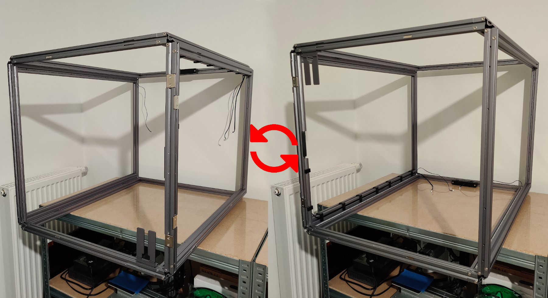
The doors are now on the desired sides, but there are some issues. The touchscreen holder and cutout on the door are at the top, and the lights and all enclosure connections are at the bottom. We need to fix that.
Front Side
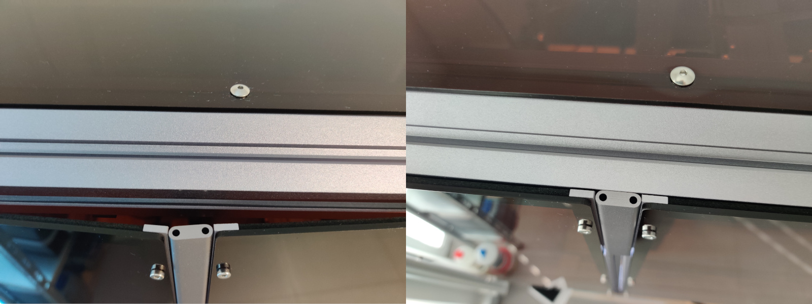
Let’s start with the touchscreen holder. The opposite beam already has screw holes for the holder. So we move the holder there, and we are done.
Now we look at the door. The touchscreen cutout needs to move to the bottom. If you notice, the acrylic panels are screwed to the door frame, and the screw positions are symmetrical. So, we can unscrew the panel and turn it upside down. If we do this, the foam insulation attached to the panel will end up on the exterior side. To fix that:
- take a razor blade and carefully remove the foam,
- get some rubbing alcohol and clean the panel from any residues,
- get some thin double-sided tape and secure the foam on the opposite side of the panel,
- place the panel back on the door frame.
Remaining Sides
If we look inside the enclosure, we will see that the enclosure converter and the LED strips are at the bottom. We need to move them to the top. We will do that by swapping each side’s horizontal beams individually.
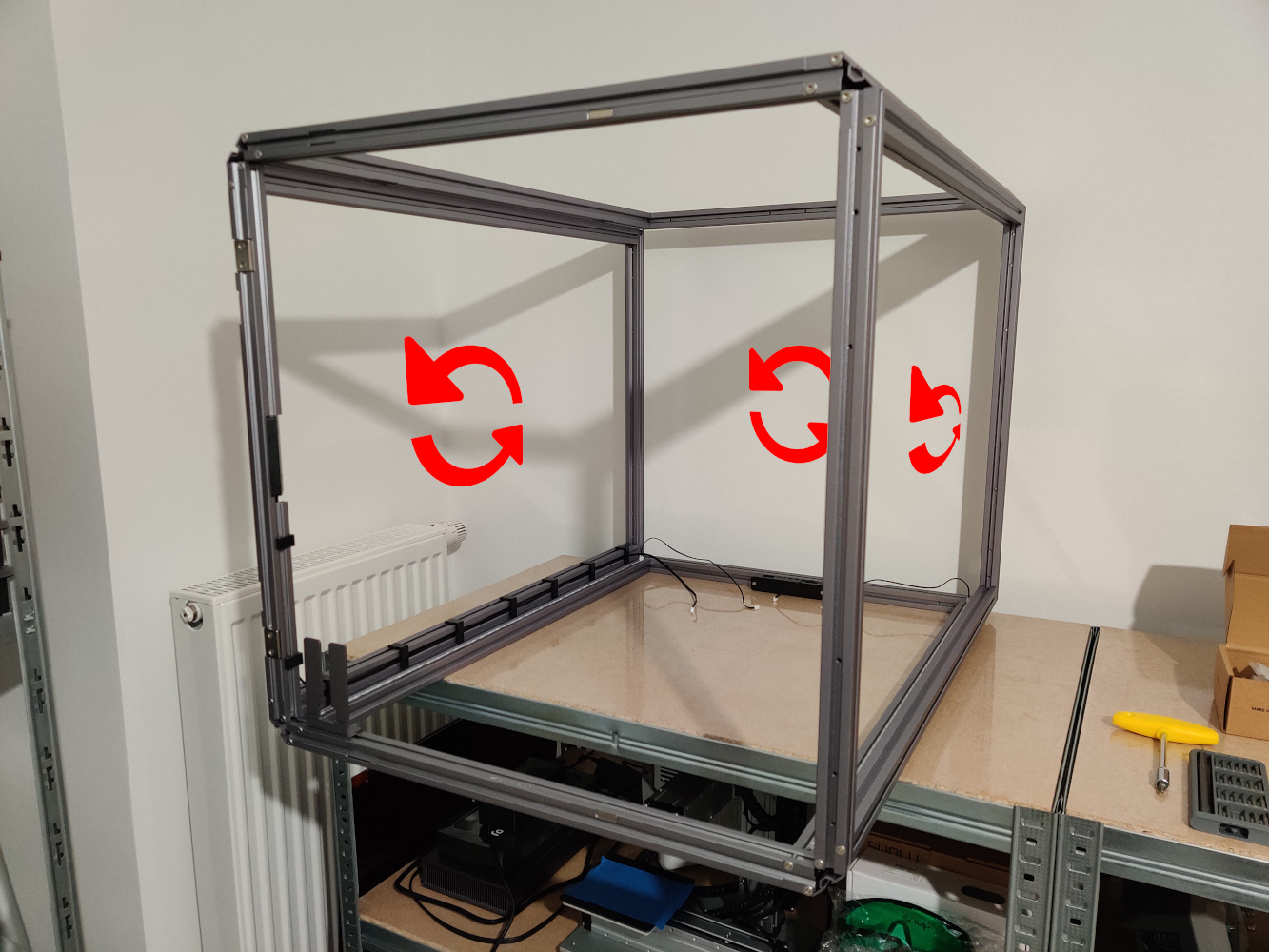
If we swap the bottom beams with the top ones, the enclosure converter and the LED strips will move to the top, but the LED strips’ connectors will be on the front side.
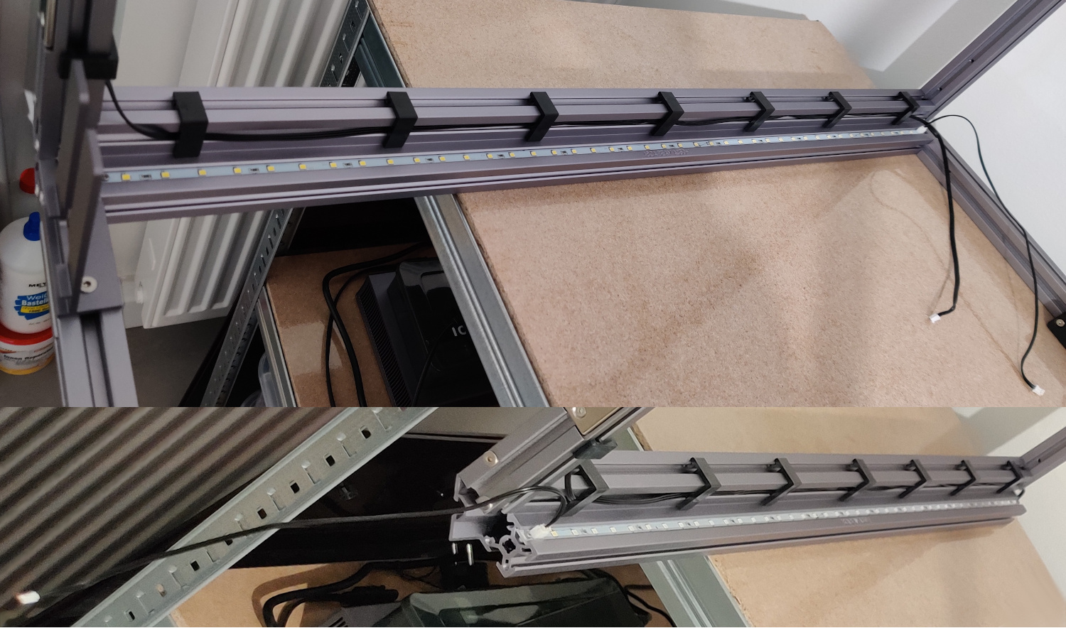
Two small screws secure the LED strips to the beams. Remove the screws, slide the strips out, rotate them, slide them back in, and secure them to the beams again with the screws.
Next, we focus on the door switches on the front left vertical beam. Since we rotated the enclosure upside down, the cable now exits the PCB enclosure from the bottom. We will route the cable from the top, so we need to make the cable exit the plastic enclosure from the top side. So, remove the screws, remove the cover, and guide the cable to the other side. At this point, you might also want to hide some of the cable inside the enclosure so that the cable has the perfect length once connected to the converter.
You could stop here and start assembling everything, but there is one more detail that you might want to address.
Side Door
Since we swapped the bottom and top beams, the magnets for the rear door hinge have moved to the front hinge position. The result is that now the door does not close completely.
Fixing that, will require some work. We need to buy new magnets, as well as open channels in the beams to install them.
Initially, I visited banggood, but I didn’t find magnets with the right dimensions \((20x5x2 mm)\). Then I went to eBay, found the magnets, ordered a pack of 10 for 6 euros, and received them in the next two days.
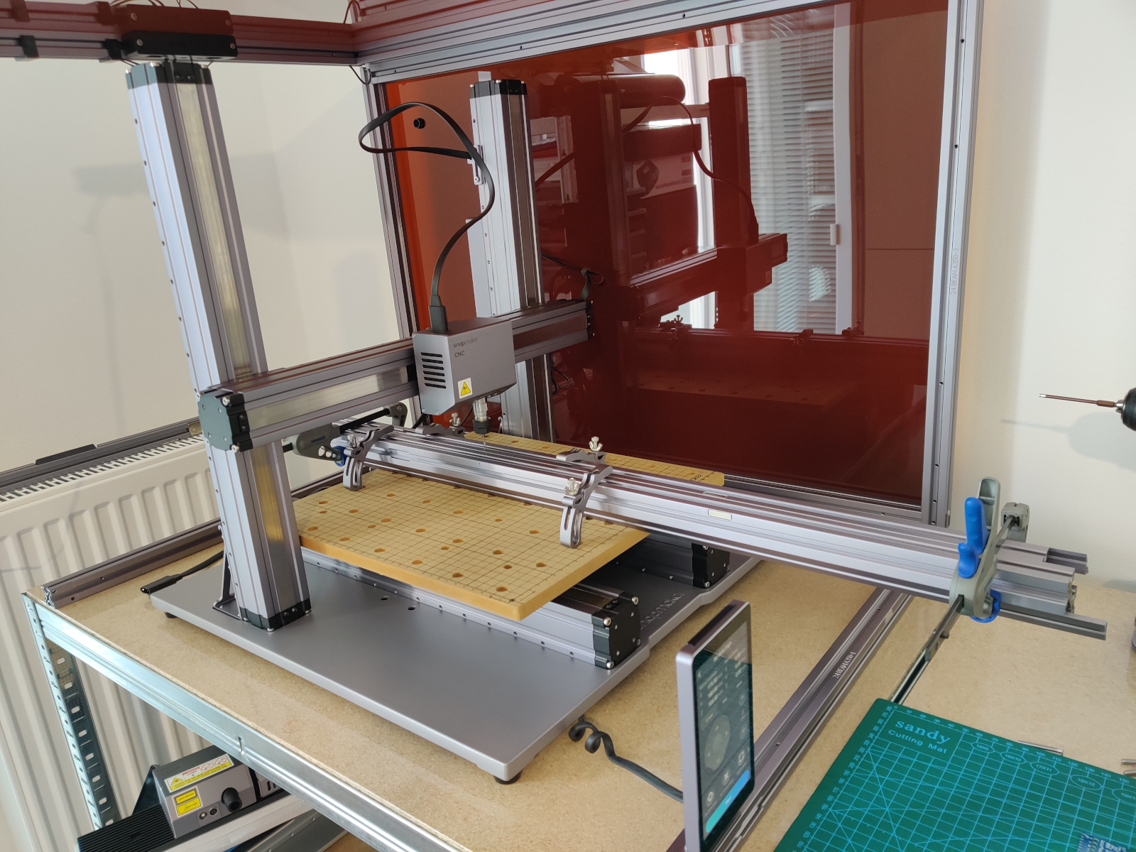
The magnets are embedded in the beams. To install the magnets, we need to remove material from the beams. If you have one, you can use a Dremel, but the result will not be clean. If only we had a machine that could do this right. Oh yeah, we do have that - time to put the Snapmaker to use.
Grab the beams, measure the exact positions of the channels, mark their centers on the beams, and mount the beams on the machine.
I wanted to take the opportunity and learn how to use Fusion 360. Using CAD would allow me to also create beveled edges around the channels. But in the interest of saving time, I went with GIMP. All you have to do is create a white rectangle on a black background and export it as an image. Once loaded in Luban, black will mean zero depth, and white will mean full depth. In Luban, position the image on the plane (depending on how you drew the rectangle, you might have to rotate the image), and go to the Process step. Select flat end mill, set target depth \(2.2 mm\), step down \(0.2 mm\), work and plunge speed \(300 mm/min\). Send the gcode to the machine and run the boundary. Double-check the boundary dimensions, as Luban doesn’t work as expected. You might have to adjust the image’s dimensions to get the right boundary size on the machine. Finally, set the work origin and start the job.
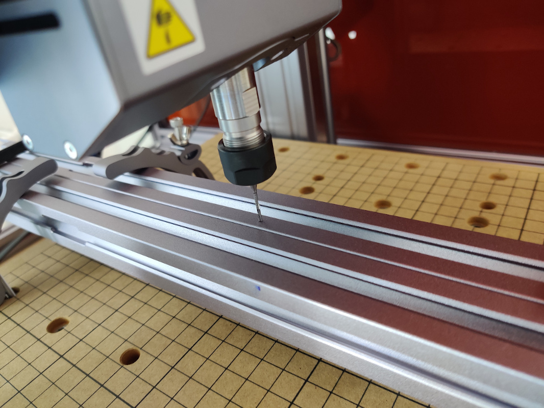
It will take less than half an hour for each channel. There can be endmill chatter at the speeds mentioned above when doing the boundary passes, so you might want to consider lowering the speeds.
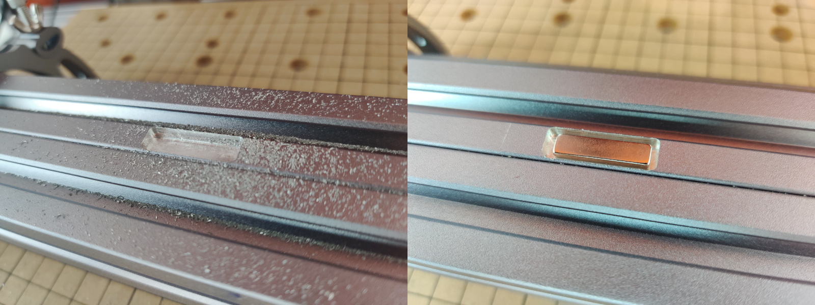
Yes, my channels were oversized. If you cannot rely on the numbers, checking the boundary by eye is only approximate. In any case, use some epoxy or other glue to secure the magnets in the channels. By the way, if you want to create a bevel on the edges, you can do it with a blade cutter by hand - aluminum cuts like butter.
Assembly
Now that we have done all the modifications, we can proceed with the assembly. Start with just the frame, and then pause there. It will be much easier if we continue by installing the machine inside the enclosure since there is still open access from all sides. Just like the enclosure, the machine is not designed to be mirrored. That means the controller will stay on the right side, and the touchscreen cable will travel across the enclosure to the front left corner. The fan will not change sides as well. Likewise, the filament holder cannot change sides, as it would interfere with the door. Personally, I don’t care about that as I keep my filament in a Sunlu FilaDryer S1.
Follow the official instructions to connect and route the cables, and fix the machine to the frame. Then install the acrylic panels and the doors, and give yourself a pat on the shoulder for a job well done.
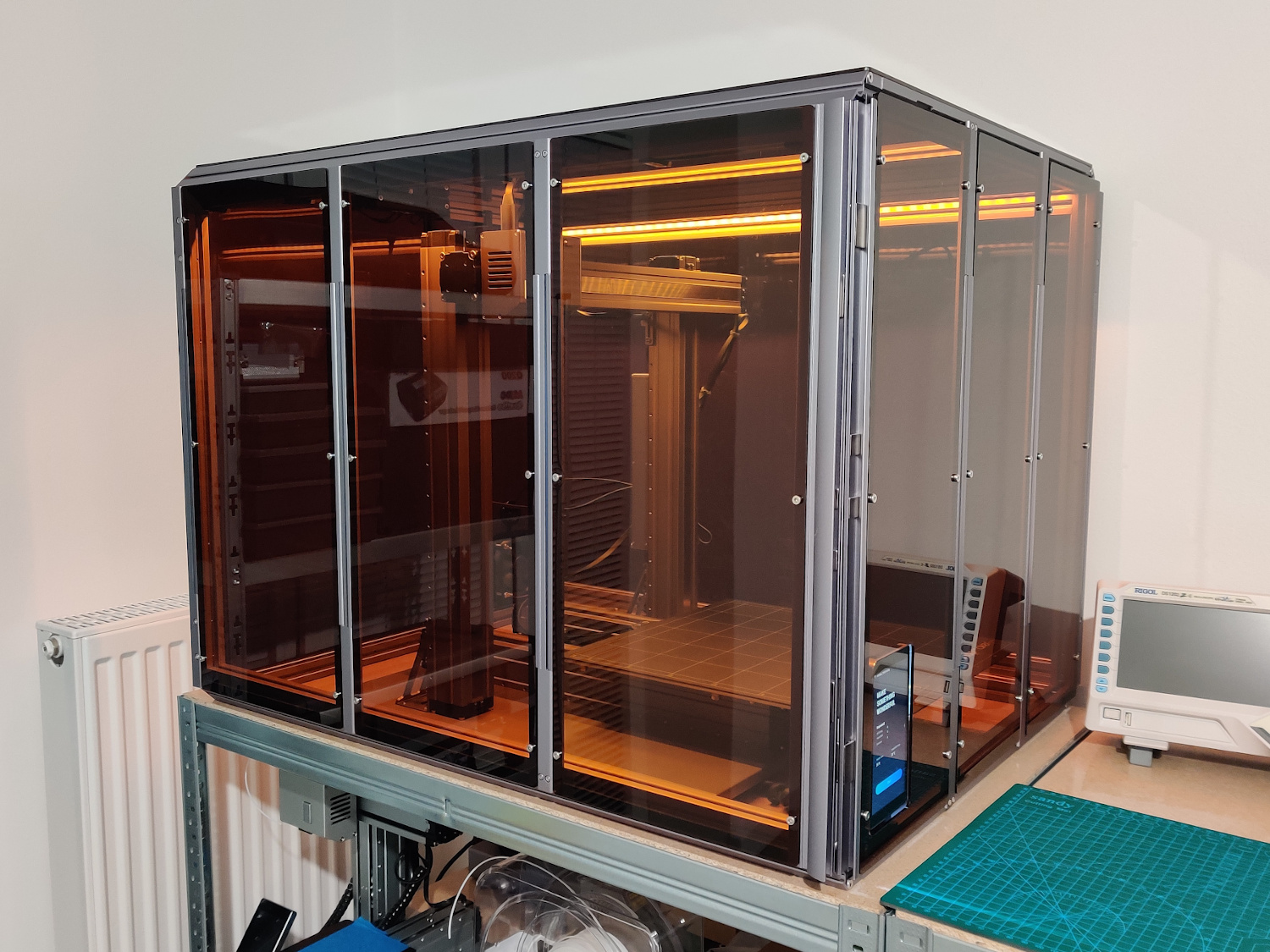
Conclusion
Isn’t it nice when you have the right tools at your disposal to do a job?! With this small build, my Snapmaker is finally installed in my kitchen… I mean professional workstation… and I can carry on with whatever project comes next. It can be considered a good machine if you can accept Snapmaker 2.0 with its quirks and shortcomings. I’ll go easy on the Snapmaker team and not criticize them too much, for now, hoping that things will improve in the future. I count on you, Snapmaker!